| Vacuum Troubleshooting |
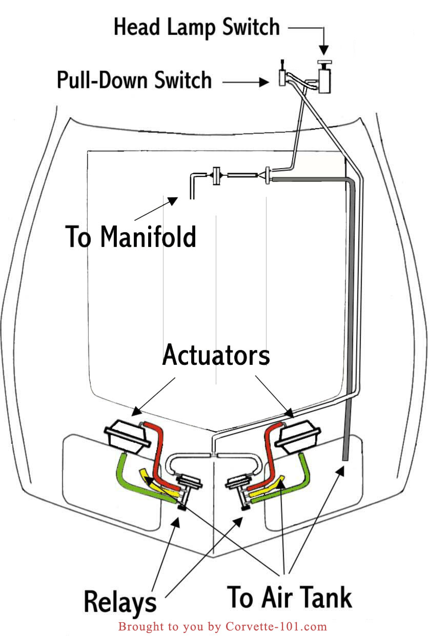
| I decided to put together a vacuum troubleshooting because their just isn't a free one on the internet I could find. I think about every C3 owner out there has had some sort of problem with their headlights opening and closing; and it's not easy to fix them without a good guide. Click on the vacuum system graphic below to enlarge for printing or to save to your hard drive. I suggest using this diagram to ensure your headlamp vacuum system is "wired" correctly before you start troubleshooting. All of the tests should be conducted with the engine off, unless otherwise indicated. |
| Tools General Function Test Vacuum Hoses Vacuum Reservoir Tank Vacuum Check Valve Vacuum Filter Head Lamp Actuators Manual Over Ride "Pull Down" Switch Head Lamp Relay Valve Head Lamp Switch |
|
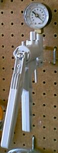
| TOOLS REQUIRED | |
|
|
|
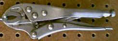 Vice Grips: Used to block a hose by clamping it. |
|
| Goto Top |
| GENERAL FUNCTION TEST |
| The headlamps should be off and closed and the pull down switch should be pushed in. Pinch closed the small white hose leading to a relay valve and the headlamp doors should open. When released, the door should close. This operation usually can only be performed once without the car running. If this test fails and your headlamps still open and close while the car is running, it simply means the system is not operating at 100 percent as designed. The following tests should help you pinpoint why this test failed. |
| Goto Top |
| VACUUM HOSES |
| DESCRIPTION: The vacuum system uses different sized black rubber hoses. Small hoses have an inside diameter of 5/32", medium 7/32" and large 9/32". The hoses should have colored stripes that correspond to colored paint dots on the vacuum system components. The colors used are red, yellow, green, white and blue. The red hoses are used to close the headlamp doors and the green hoses are used to open them. Yellow hoses are used for the vacuum supply or holding tank. The small white hoses are signal hoses; they signal the relay to open or close. The small blue hoses are used to connect the pull down switch with the headlamp switch. |
| TROUBLESHOOTING: First used the diagram above to ensure the vacuum system is "wired" correctly. This includes checking for kinks, pinches and holes. Plug one end of the hose (I use a bolt a little bigger than the inside diameter of the hose) and connect the other to a vacuum pump. If the vacuum pressure drops, the hose has a leak and should be closely examined for damage. If the hose is damaged, replace it. But don't throw it away, you may be able to salvage some of the hose for use elsewhere. |
| Goto Top |
| VACUUM RESERVOIR TANK |
| DESCRIPTION: The 73-79 models use a long cylindrical steel tank with three brass fittings screwed into the surface that function as large vacuum ports. |
| LOCATION: The tank is part of the front bumper mounting brackets; therefore a front end accident can cause the tank to fail. |
| FUNCTION: The vacuum tank provides a source for a vacuum supply when the engine is not running. |
| TROUBLESHOOTING: Plug two of the vacuum ports and connect the vacuum pump to the third. The tank should maintain a vacuum. If the tank will not hold a vacuum, then it can be replace or possible repaired. |
| Goto Top |
| FUNCTION: The check valve enables the vacuum tank to store a vacuum supply when the engine is not running by preventing air from escaping. |
| TROUBLESHOOTING: The check valve permits air to flow in one direction. Air can only pass from the side with the 2 ports, towards the side with the single port. You should be able to blow into either of the 2 ports opposite the single port. These 2 ports should hold vacuum when attached to a vacuum pump as long as the adjacent port is plugged. The end with the single port should not maintain vacuum pressure and you should not be able to blow air into this port. A leaking check valve may cause the headlamps to open when the engine is turned off; but this depends on the condition of the rest of the headlight vacuum system. A bad check valve, where air travels in both directions, will allow all the air to escape from the holding tank and prevent operation of the headlights while the car is turned off. A clogged check valve will prevent vacuum from being supplied to the system. |
| Goto Top |
| VACUUM FILTER | |||
|
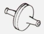 |
| FUNCTION: The filter prevents contaminating particles from entering the engine. |
| TROUBLESHOOTING: Hold the filter up to bright light, and look into the ports to examine the filter. If it is extremely soiled, it should be replaced with a new one. Ensure it is replaced the in the same orientation as is was removed or particles in the filter will be sucked into the engine. A cracked or leaking filter may allow dirt particles into the engine, and will cause a vacuum leak. |
| Goto Top |
| HEAD LAMP ACTUATORS | Click here for a diagram of internal actuator operation. | ||
|
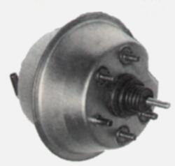 |
| FUNCTION: The headlamp actuators open or close the headlamp doors. More specifically, the green hose opens the headlamp doors and red closes them. |
| TROUBLESHOOTING: Perform the following two
steps in order. 1. With headlamps in the closed position, disconnect the large red hose and attach the vacuum pump. If the vacuum pressure holds, the internal diaphragm is good. If the vacuum pressure drops, the internal diaphragm is leaking and the actuator must be replaced. 2. With the headlamps in the open and locked position (if the headlamps will not open normally, try opening them manually by pushing them up from the front underside of the vehicle), disconnect the large green hose and attach the vacuum pump. If vacuum pressure holds, the internal diaphragm and rear sealing grommet are both good. If the vacuum pressure drops, replace the grommet. NOTE: If you do not open the headlamps prior to this test, applying vacuum to the port should slowly open the headlamps until they are completely open. At this point this port should hold a vacuum. |
| Goto Top |
| MANUAL OVER RIDE "PULL DOWN" SWITCH | |||
|
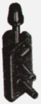 |
| FUNCTION: The headlamp actuators open or close the headlamp doors. |
| TROUBLESHOOTING: With the switch closed (pushed up) attach the vacuum pump to the blue and block the white port; vacuum pressure should hold. Following this, open the switch (pull it down), a vacuum should still be maintained. If you unblock the white port, you should be able to look into it and see daylight. |
| Goto Top |
| HEAD LAMP RELAY VALVE | |||
|
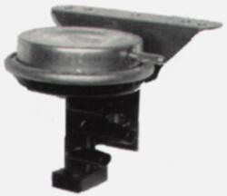 |
| FUNCTION: Relay valves control vacuum to the headlamp actuators to open and close the doors. |
|
TROUBLESHOOTING: Disconnect all 4 vacuum
hoses. Remove the filter at the base of
the relay and inspect it for damage and to make sure it isn't clogged.
If it is clogged, the headlamp doors may open slowly. If you this test fails, check out the Headlamp Relay Repair article in A&W's Vette |
| Goto Top |
| HEAD LAMP SWITCH | ||
|
| FUNCTION: The headlamp switch turns the headlamps on and off and signals the vacuum components to open or close the head lamp doors. |
| TROUBLESHOOTING: When closed (knob pushed in) attach the vacuum pump to port 2 and block port 3. Vacuum pressure should be maintained. When open (knob pulled out), port 3 will not hold vacuum. Attach the vacuum pump to port 2. vacuum pressure should hold. |
| Goto Top |